
LANGUAGES
TO-CIRCUIT.
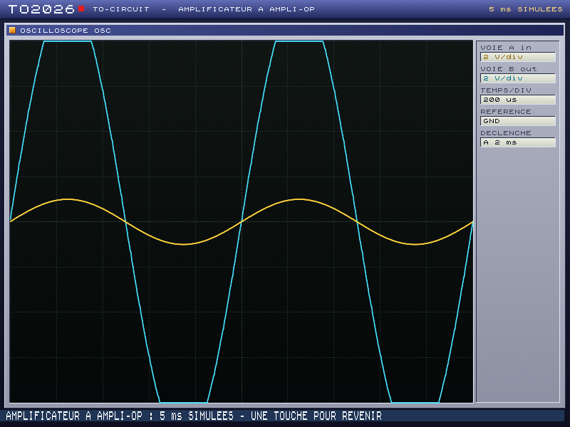
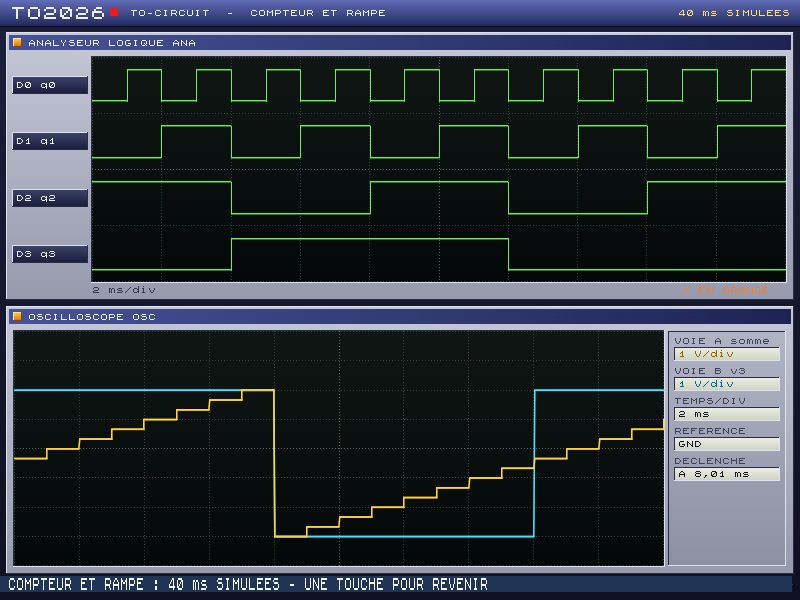
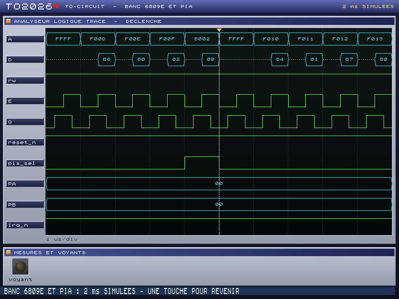
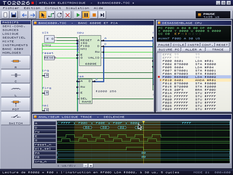
The electronics workbench, on a cartridge. You describe the circuit, one component per line: resistors, capacitors, sources, diodes, op-amps, logic gates, and even a real 6809E with its memory and its PIA. The machine simulates it, then shows its instruments as on a lab bench: oscilloscope, logic analyzers, multimeters, LEDs and lamps. And the WORKBENCH builds the same circuit with the mouse, with the instruments moving live.
The complete language reference (in French)
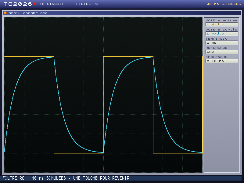
circuit "Filtre RC"
PULSE gen (entree, GND) low=0V high=5V freq=100Hz
R r1 (entree, sortie) value=1kohm
C c1 (sortie, GND) value=1uF
SCOPE osc (entree, sortie, GND) time=2ms volts=1V
run 40ms
The language
- One component per line:
TYPE name (node, node, ...) key=value; two pins with the same node name are connected - Analog:
R,C,L,POT,SWITCH,DC,SINE,PULSE,DIODE,LED,OPAMP - Logic:
BIT,CLOCK,NOT,AND,OR,XOR,NAND,NOR,DFF,COUNT4,LAMP, with four states: 0, 1, X and Z - The bridges
A2DandD2A, and the instrumentsSCOPE,LOGIC,LA,METER - Buses (
bus A[15:0]) and the 6809E bench:M6809E,ROM8,RAM8,PIA6821,DECODE,PHASE09,RESET09,PULL
The cartridge
RUNsimulates the circuit and shows the readout of its instruments in 800 × 600; a key brings back the prompt, which prints the measurements, andVOIRshows the readout againEDITopens the editor, with the language colours; an error names its line and its componentAIDE R,AIDE SCOPE...: the pins and keys of each component;INFOandMESURESsum upRUN "3:FILTRE", and likewiseCOMPTEUR,LED,REDRESSE,AMPLI,DEMIADD,SEUILandBANC6809: eight circuits on the system disk
WORKBENCH
- The circuit as a schematic: a palette, components you place, move and wire with the mouse; the text stays the reference and is rewritten at each gesture
- Live simulation, wires coloured by their voltage or level; a click flips a switch, the wheel turns a potentiometer
- The 6809E debugger: disassembly, registers, breakpoints, single cycle or single instruction, and a click in the analyzer finds the instruction behind an access
- Load a ROM on the bench, with its SHA-256 fingerprint and its reset vector
A lab bench in the machine
In the days of the Thomson computers, electronics was learned with a soldering iron, a breadboard and an oscilloscope lent by the school. TO-CIRCUIT keeps that approach: build, measure, understand, then change a value and try again. The simulation is made for the machine: nodal analysis for the voltages, events for the logic, and the 6809 of the ASSEMBLEUR cartridge replayed on the wires. Its models are deliberately simple, so that you see what a circuit does rather than the fine points of a real component.